Introduction
In 1987 a group of member companies of the Society of the Plastics Industries began development of a communication protocol for use by their processing and auxiliary equipment. Their goal was to allow the exchange of information between various pieces of equipment from different manufacturers to be simple and reliable. The result of their work was released in 1990 and has made the interconnection of equipment much easier and straightforward. There are now over 40 companies that offer the SPI Protocol in their products.
Protocol Basics
The SPI Protocol is described by a 2 part specification. The largest portion of the SPI Protocol specification deals with how basic information is exchanged between equipment. The second part of the specification details the actual pieces of information exchanged using the protocol. Items such as Process Temperature, Process Setpoint and Process Status are detailed in this part. This FYI will list the commands that are supported by Advantage equipment.
Equipment Setup
The setup of equipment to be connected in an SPI Protocol network is simple. Each device must have a unique address for its device type and it must use the same data transfer rate as the other pieces of equipment in the network. There are many acceptable ways used to ‘set’ the device address and data rate. Advantage equipment provides access to the information via the front panel operators and displays. Other manufacturers may use internal DIP switches or jumpers. A typical cell may be configured as follows:
- Data Transfer Rate: 9600 bits per second (bps)
- Mold Temperature Controller (Qty 2): Addresses 1 and 2
- Chiller (Qty 1): Address 1
Note in the above example that different device types may have the same address. This is because the SPI Protocol uses the device type as part of its internal address.
Network Troubleshooting
Troubleshooting a network is best done by verifying the setup of each piece of equipment and insuring that the network is installed with the correct electrical interconnection. Here are some basic things to do if equipment isn’t ‘talking’ as expected.
- Verify that each piece of equipment is properly grounded to its power source.
- Inspect cables inside and outside the electrical cabinet. Repair or replace as necessary. The cable scheme used by most manufacturers allows the communication signals to ‘pass through’ each piece of equipment. Therefore, when a piece of equipment is disconnected from the middle of the network, all the equipment ‘after’ that one will be disconnected, too. If a piece of equipment is being permanently removed, the device cables should be rearranged at the molding machine to reconnect the other equipment.
- Check the Data Transfer Rate and Address of each piece of equipment. For example, if both Temperature Controllers have the same address, they will both try to ‘talk’ at the same time and garble each other’s data.
- Verify the network is properly terminated and that it is configured as a ‘multi-drop’. This is best achieved by following the molding machine manufacturer’s installation instructions and use extension cables provided by them or us.
- Attach each device, singly, to the molding machine and see if it ‘talks’. Add additional devices until a problem is seen.
SPI Register Definitions for Sentra Temptender, Sentra G, Sentra G-300 & Sentra T-300 Control Instruments
Poll
Select
C1
C2
C1
C2
Command
Description
20
20
20
21
Echo
Controller integrity command
20
20
Version
Controller Version Command
20
30
20
31
Setpoint
Desired process temperature
20
32
High Temp
Hi temperature deviation alarm
20
34
Low Temp
Low temperature deviation alarm
20
36
20
37
Flow Alarm
Low flow alarm setpoint
20
40
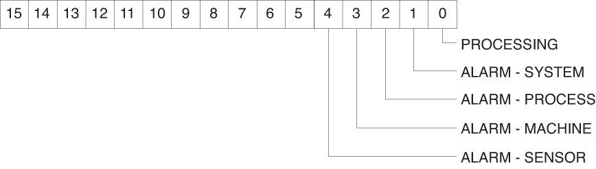
Status Process

Poll
Select
C1
C2
C1
C2
Command
Description
20
42
Status
Machine 1

Poll
Select
C1
C2
C1
C2
Command
Description
20
4A
20
4B
Protected mode
- machine

Poll
Select
C1
C2
C1
C2
Command
Description
20
70
Temperature
To process
20
72
Temperature
From process
20
78
Flow rate
From unit GPM
20
E0
Blanket Poll
Returns:
20
30
Setpoint
20
22
High alarm deviation
20
34
Low alarm deviation
20
40
Status process
20
70
To process temperature
Poll
Select
C1
C2
C1
C2
Command
Description
20
44
Status
Machine 2

SPI Register Definitions for Maximum MG, MK-LE & MK-HE Control Instruments
Poll
Select
C1
C2
C1
C2
Command
Description
20
42
Status
Machine

Poll
Select
C1
C2
C1
C2
Command
Description
20
44
Status
Machine 2
Poll
Select
C1
C2
C1
C2
Command
Description
20
48
20
49
Machine

Poll
Select
C1
C2
C1
C2
Command
Description
20
20
20
41
Echo
Controller integrity command
20
20
Version
Version Controller version command
20
30
20
31
Setpoint
Desired process temperature
20
32
High temp
Hi temperature deviation alarm
20
34
Low temp
Low temperature deviation alarm
20
36
20
37
Flow Alarm
Low flow alarm setpoint
20
40
Status
Process

Poll
Select
C1
C2
C1
C2
Command
Description
20
E4
Remote temperature
(version 1.12 & above)
20
E6
Evaporator temperature
(version 1.12 & above)
20
E8
Media temperature
(version 1.12 & above)
20
EA
20
EB
Freezestat temperature
(version 1.12 & above)
